
The engineering principles of the engine are described below. The drawings are only intended to show that there is nothing in principle to stop such an engine from being built.
The drawing ‘Slideshow’ (Fig 1) below shows a precessing offset gyro as seen from above.
Drawing no 1 shows the initial configuration. The mechanism is rotating about the point A (the black dot) and the rotor is just starting to retract.
Still rotating about the point A in drawing no 2, the rotor has retracted further.
Drawing no 3, still rotating around A and has retracted some more.
Same in drawings 4 and 5.
In 6 it all changes. The bar (C) stops rotating and the gyro rotates about the point B (the white dot).
This is the “wrapping” (in this case, un-wrapping) phenomenon, where the point of rotation moves towards (in this case away from) the mass, rather than the mass moving towards the point of rotation. This of course is the essence of the invention… the discovery that total energy does not change in this situation. The maths is provided below (maths is complete, just needs digging out.)
When it reaches the position shown in 7, the bar starts to rotate again, but this time about the point B, and the gyro starts to retract again.
In 8, 9, 10 and 11, the gyro continues to retract and the bar C continues to rotate about B.
At the instant that the gyro is fully retracted, the bar (C) stops rotating and the gyro starts to rotate about A.
In 13, it is back to its initial starting configuration and the cycle repeats.
In drawings 1 to 5, energy is put into the system in order to retract the gyro wheel.
In drawings 6 and 7, no energy is lost by the system.
In drawings 8, 9 10 and 11, energy again has to be put in.
In 12 and 13, again no energy is given up by the system.
Thus the energy of the system continuously increases. The energy is manifest as an increase in height of the rotor – it lifts. This is shown in figs 2 and 3.
Slideshow
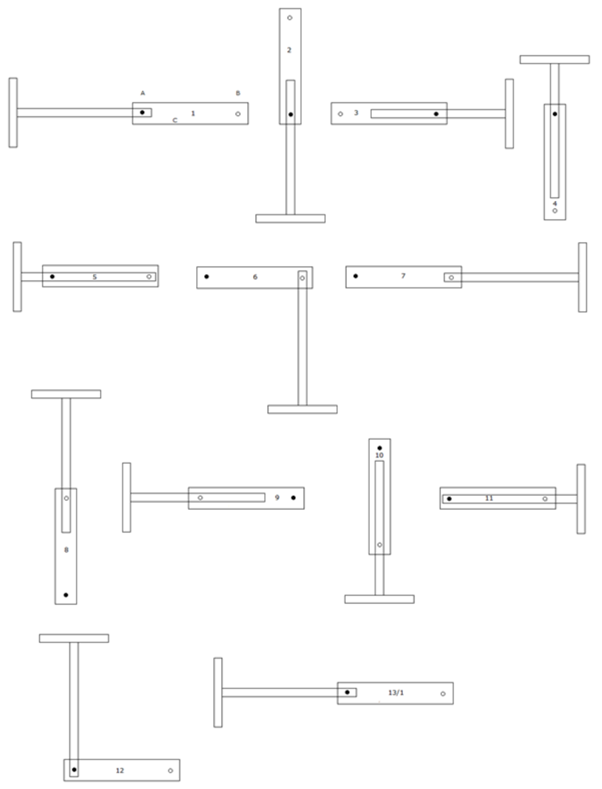
Fig 1
Side views
Fig 2 below is the side view of position 1 in the slideshow. This is the initial position just after the gyro has started to precess. A mechanism would be needed to allow the gyro to nutate briefly before settling into natural precession. Forced precession will not work; the gyros’ ADG must be zero at this initial stage and the only way to achieve that is to let it nutate and precess naturally. The gyro is precessing around the black axle and just starting to retract. The axle is attached to the frame at the point ‘a’ . The white axle is of variable length and at this point is shortened so as to allow the precession about the black axle, and also not interfere with the retraction. The top black axle is attached to the top plate at ‘b’ and controls its rotation.
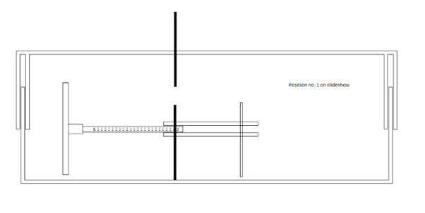
Fig 2
In fig 3 the gyro has lifted in the gravitational field, but the frame has not. The gyro is still precessing about the black axle. The top black axle has shortened to allow the gyro to rise.
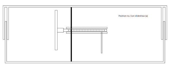
Fig 3
Then, as shown in fig 4, the lower black axle disengages from the gyro axle and the white axle engages with the gyro axle and is now attached to the frame at ‘c’ so that the gyro can now start to rotate about the white axle – thus exploiting the wrapping phenomenon. At the same time the top half of the frame rises, driven by the top black axle as it pushes down on the gyro axle top plate.
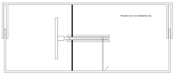
Fig 4
In fig 5 the lower black axle has shortened to allow the rotation about the white axle, and the white axle has shortened, lifting the lower half of the frame. So the sequence is… gyro rises, top half of frame rises by pushing down on the gyro, lower half of frame is lifted by pulling it up towards the gyro.
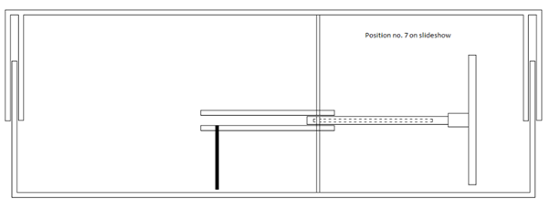
Fig 5
Then the gyro precesses around the white axle as it retracts, and thus rises in the gravitational field again as shown in fig 6.
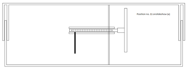
Fig 6
Then as shown in fig 7, the frame is lifted by the upper white axle pushing down on the gyro upper plate The lower black axle connects with the frame so that the gyro can rotate about this axle and the lower white axle shortens so that rotation about the black axle is not impeded.
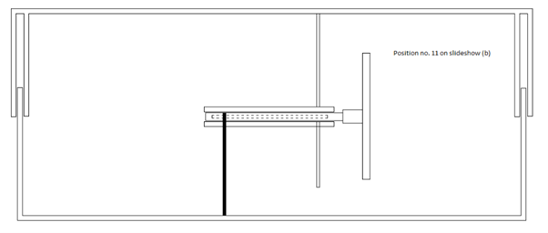
Fig 7
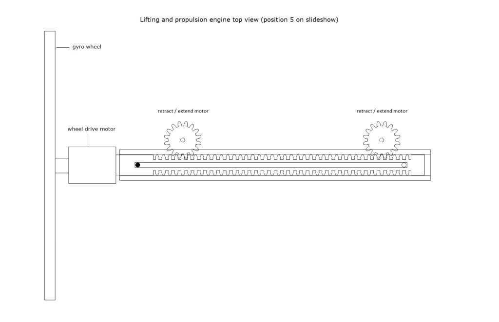
Fig 8 A more detailed view of the retract mechanism
Test comment 180923